
Data Link Layer is the second layer of the OSI model in computer networking, OSI is a seven-layer model that refers to the Open Systems Interconnection model. Data Link Layer (DLL) defines the format of data on the network. We have shared all the details about the Data Link Layer in this article.
Topics discussed in this article are as follows;
- What is DLL in Computer Network?
- Functions
- Flow Control
- Designs Issues
- Techniques of Flow
- Error Control Mechanism
- Automatic Repeat Request (ARQ)
➤ What is Data Link Layer in Computer Network?
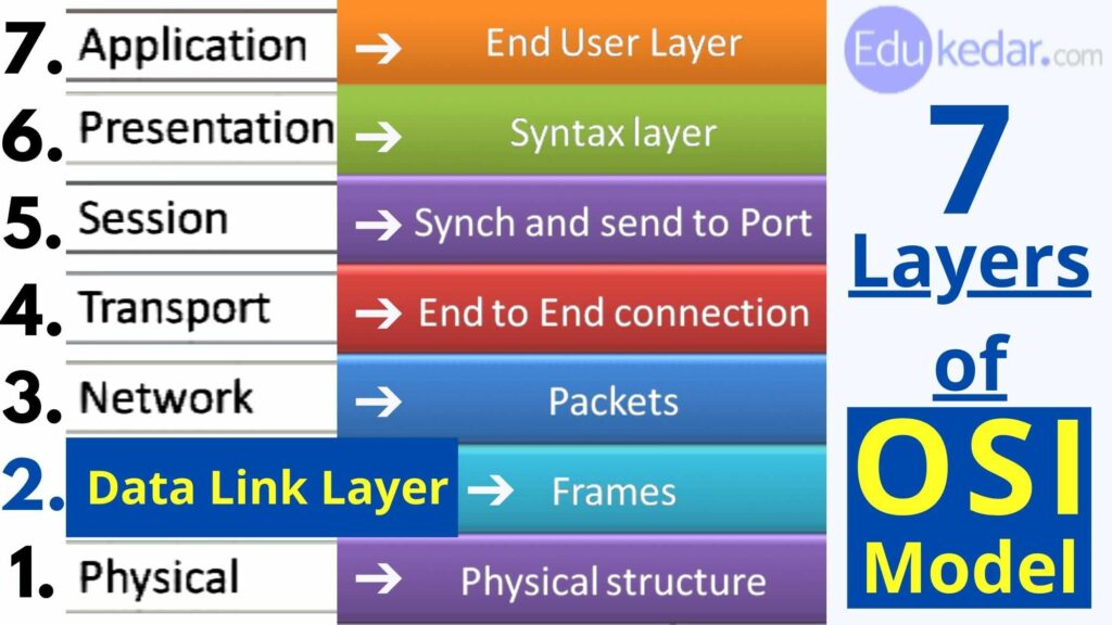
Data Link Layer is also known as Data Link Frame or layer-2. It is the 2nd layer of the seven-layered OSI Model.
Data Link Layer work is to make the communication on the physical link reliable and it provides physical addressing and media access.
It is responsible for the most reliable data transfer from node to node. It creates frames from packets received from the network layer and sends them to the physical layer.
It also synchronizes the data that will be transmitted over the network. Controlling errors is simple. The encoded data is subsequently sent to the physical world.
The data link layer employs error detection bits. It also corrects any mistakes.
Purpose of Framing in Computer Networks
Frames are created from incoming messages. After that, the system waits for acknowledgements to arrive following the transmission. It is a safe way to convey a message.
- The data link layer’s principal purpose is to convert a raw transmission facility into a line that looks to the network layer to be free of undetected transmission defects.
- The sender performs this duty by breaking up the incoming data into data frames (usually a few hundred or thousand bytes).
- And then transmitting the frames in sequential order.
- The receiver confirms accurate receipt of each frame by sending back an acknowledgement frame if the service is reliable.
- Frames are the streams of bits received from the network layer that is converted into manageable data units.
- The Data Link Layer is in charge of dividing the stream of bits.
If the frames are to be sent to multiple systems on the network, the Data Link layer adds a header to the frame to identify the physical address of the sender or recipient of the message.
➤ Functions of Data Link Layer
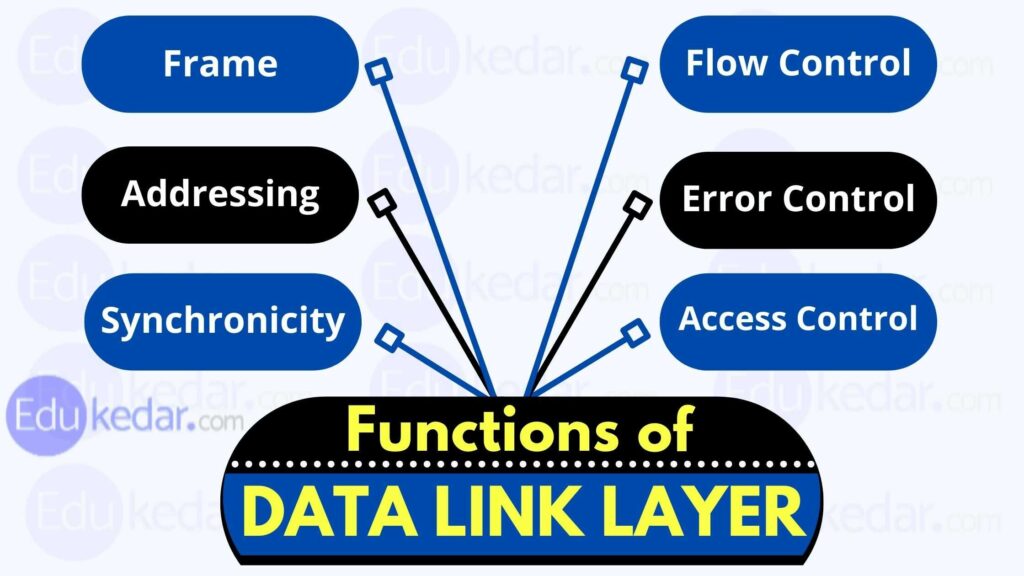
There are many functions are performed by the data link layer on behalf of the top layer in the OSI Model of Computer Networking.
Data Link Layer major functions are as follows:
⦿ Creating a frame
The Data-Link Layer encapsulates packets from the Network Layer into Frames.
Then it transmits each frame to the hardware bit by bit. The data connection layer at the receiver’s end collects signals from hardware and assembles them into frames.
⦿ Physical Addressing
Layer-2 hardware addressing is provided by the data-link layer. On the connection, the hardware address is presumed to be unique. At the moment of manufacture, it is programmed into hardware.
⦿ Synchronicity
In order for data frames to be transferred over the network, both machines must be synced.
⦿ Error Control in Data Link Layer
Signals may experience problems during the transition and the bits may be inverted.
These faults are recognized, and actual data bits are attempted to be recovered. It also provides a means for the sender to report errors.
⦿ Flow Control in Data Link Layer
The speed and capacity of stations on the same link may vary. The data-link layer provides flow control, allowing both machines to communicate data at the same time.
⦿ Multiple-Use
When a host on a shared link tries to send data, there’s a good chance they’ll collide. The data-link layer provides mechanisms such as CSMA/CD that enable many systems to access a shared media.
The data-link layer is in charge of implementing point-to-point flow and error control.
⦿ Access Control
When sending a data frame (Layer-2 data) from one host to another across a single medium, the transmitter and receiver must both operate at the same speed. That is, the transmitter provides data at a rate that the recipient can process and accept.
What if the sender’s or receiver’s speed (hardware/software) differs? If the transmitter sends too quickly, the receiver may get overburdened (swarmed), and data may be lost.
Must Read ➜ Recursion Function in Python
➤ Flow Control in Data Link Layer:
Flow control is a mechanism that prevents a rapid transmitter from driving a slow receiver by buffering the additional bit. This avoids a traffic block on the receiver’s end.
Error control is accomplished by including a trailer at the end of the frame. The use of this approach also prevents frame duplication. Data Link Layers provide a technique to prevent frame duplication.
When two or more devices are connected to the same link, access control protocols determine which device has control over the link at any particular time.
In the ISO-OSI Model, there is a Data Link Layer.
➤ Design Issues of Data Link Layer
The problem at the data link layer (and much of the upper layers) is how to protect a fast transmitter from inundating a slow receiver with data.
To let the transmitter know how much buffer space the receiver has at any given time, a traffic regulation device is frequently required.
Flow regulation and error management are frequently combined.
In the data connection layer, broadcast networks face an additional challenge: controlling access to the shared channel.
This problem is addressed by the Medium Access Control (MAC) sublayer of the data link layer.
➤ Techniques of Flow Control
There are various techniques that can be used to control the flow in Data Link Layer.
⦿ Stop and wait
After delivering a data frame, this flow control mechanism causes the sender to pause and wait for the acknowledgement of the data frame delivered.
The sender and the receiver, both agree on the number of data frames after which the acknowledgement should be transmitted in this flow control method.
As we’ve seen, the stop and wait flow control technique wastes resources, thus this protocol strives to make the most of the underlying resources.
⦿ Error Control
When a data frame is transmitted, it is possible that it will be lost in transit or may be received corrupted. The recipient does not receive the correct data frame in both circumstances, and the sender is unaware of the loss.
In this situation, both the transmitter and the receiver are equipped with protocols that assist them in detecting transit faults such as data-frame loss. As a result, either the sender or the recipient may request that the prior data frame be resent.
➤ Error Control Mechanism:
Error detection in Computer Networks :
The sender and receiver, or both, must determine whether or not there is an error in the transmission.
When the receiver receives a proper frame, it should acknowledge it with a positive NACK.
When the receiver receives a broken or duplicate frame, it returns a NACK to the sender, requiring the sender to retransmit the right frame.
Retransmission in Computer Networks:
The sender keeps track of time and establishes a timeout period. If the acknowledgement of a previously transmitted data frame does not arrive within the timeout, the sender retransmits the frame, believing that the frame or its acknowledgement has been lost in transit.
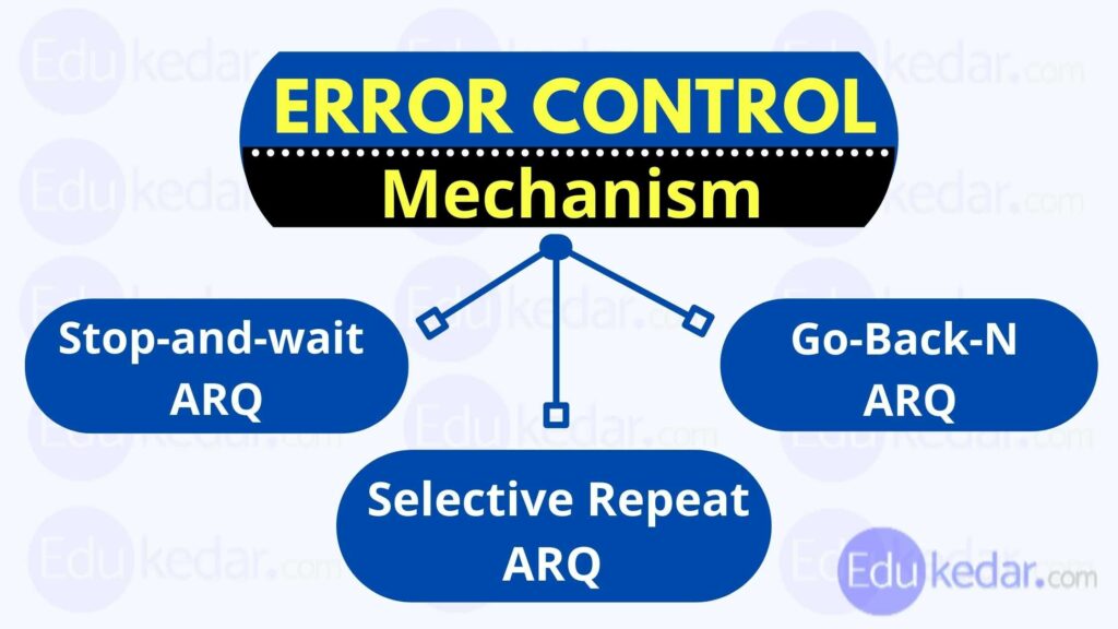
To control the mistakes caused by Automatic Repeat Requests (ARQ), the Data-link layer can use one of three techniques:
- Stop-and-wait ARQ,
- Go-Back-N ARQ,
- Selective Repeat ARQ (Transition in stop and wait)
⦿ Stop-and-wait ARQ
The sender starts the timeout count when a frame is sent.
The sender transmits the next frame in the queue if the sender receives acknowledgement of the frame in a timely way.
If the sender does not get acknowledgement within a reasonable period, the sender assumes the frame or its acknowledgement has been lost in transit. The sender retransmits the frame, and the timeout counter is reset.
The frame is resent if the sender receives a negative acknowledgement.
⦿ GO BACK-N ARQ:
Take a moment to catch your breath. The ARQ method does not make the most efficient use of the resources available. The sender does nothing when he or she receives the acknowledgement. In the Go-Back-N ARQ mechanism, both the transmitter and the receiver keep a window open.
Back-n-ARQ is a command that allows you to go back in time.
The command Back-n-ARQ allows you to travel back in time.
The sender can send multiple frames without having to wait for the previous ones to be acknowledged because of the sending window size. The receiver can receive and acknowledge several frames using the receiving window. Each arriving frame’s sequence number is recorded by the receiver.
The sender checks to verify which sequence number it has received affirmative acknowledgement for after sending all of the frames in the window. If all of the preceding frames have been positively acknowledged, the sender sends the next batch of frames. If the sender receives NACK or no ACK for a particular frame, it must retransmit all of the frames until it obtains a positive ACK.
⦿ Selective Repetition ARQ :
In Go-back-N ARQ, the receiver is thought to have no buffer capacity for its window size, therefore each frame must be processed as it arrives. Any frames that have not been recognized must be resent as a result of this.
The receiver buffers the frames in memory while keeping track of the sequence numbers and transmits NACK for just the frames that are missing or damaged in Selective-Repeat ARQ. In this case, the sender only sends packets that have received NACK.


