
Open System Interconnection (OSI) Model has seven-layer and Physical Layer is the lowest layer and is concerned with wiring and electrical standards. It provides an unreliable bit transmission/reception service to the Data Link layer. Here in this article, we have shared what are the functions of the Physical layer and other basic details about this layer.
What is Physical Layer in OSI Model?
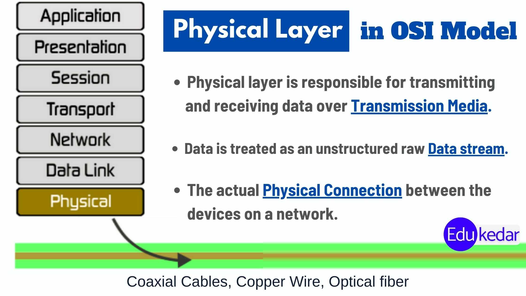
The physical layer is the lowest layer in the 7 layers of the OSI model. It is in charge of transmitting messages and data from one computer to another.
Physical Layer isn’t concerned with the meaning of the bits; instead, it’s concerned with the physical connection to the data link network, as well as signal transmission and reception.
7 Layers of OSI Model
- Application Layer
- Presentation Layer
- Session Layer
- Transport Layer
- Network Layer
- Data Link Layer
- Physical Layer
Physical Layer Protocols
- A physical protocol is a set of rules that governs the data communications between computers on a network.
- Networking Protocols and rules include guidelines that regulate the characteristics of a network such as access method, allowed physical topologies, types of cabling, and speed of data transfer.
- Examples of Physical layer protocols include Fiber cables, Integrated Services Digital networks, Ethernet, Universal Serial Bus(USB), Bluetooth, Controller Area Network.
In the OSI model, the physical layer interacts with actual hardware and signaling mechanisms. The physical layer of the OSI network model is the only one that deals with the physical connection between two separate stations.
This layer specifies the hardware, cabling, wiring, frequencies, and pulses that are utilized to represent binary signals, among other things.
The Data-link layer receives services from the Physical layer. They are converted to electrical pulses, which represent binary data, by the physical layer. After that, the binary data is transferred across the wired or wireless medium.
Transmission Media in Physical Layer
Transmission media refers to the medium used to send data between two computer systems. There are two types of transmission media.
- Guided Media – Copper wire, Fiber optic cables
- Unguided Media – wireless (Radio-frequency, Microwave)
Guided Media
All communication wires/cables, such as UTP, coaxial cables, and fiber optics, are guided media. The sender and receiver are directly connected in this medium, and data is sent (directed) through it.
Unguided Media
Because there is no connection between the transmitter and receiver, wireless or open air space is considered unguided media. Information is disseminated across the air, and anyone, including the intended recipient, can acquire it.
Must Read ➜ Application Layer Protocols
Messages in Physical Layer
Data must first be transformed into electromagnetic signals before being delivered via physical media. Data might be analogs, such as human speech, or digital, such as a disk file. Digital and analog signals can be used to represent both analog and digital data.
Digital Signals in Analog Signals
Digital signals are discrete and consist of a series of voltage pulses. Within the circuitry of a computer system, digital signals are utilized.
In nature, analog signals have the shape of a continuous wave and are represented by continuous electromagnetic waves.
Transmission Impairment in Data Communication
Signals tend to decay as they travel across the medium. This could be due to a variety of factors, including the following:
Attenuation of sound
- The signal must be powerful enough for the receiver to accurately comprehend the data.
- When a signal travels through a medium, it becomes weaker.
- It loses strength as it travels further.
- The dispersion of information
- Signals tend to spread and overlap as they travel through the media. The amount of dispersion is determined by the frequency.
Distortion due to delay
Signals are conveyed at a predetermined pace and frequency across media. If the transmission speed and frequency do not match, the signal may arrive at its destination in an unpredictable manner. It is crucial in digital media that some bits arrive before those that have already been delivered.
Make a lot of noise
Noise in signal is a random disturbance or fluctuation in an analog or digital transmission that might affect the real information being transmitted. Noise is classified into one of the following categories:
Noise from the Heat
Heat agitates a medium’s electronic conductors, perhaps introducing noise. Thermal noise is unavoidable up to a certain point.
Intermodulation is a phrase used to describe the process of When various frequencies use the same medium, interference can result in noise. When two different frequencies share a medium and one of them has excessive strength or the component itself isn’t working properly, intermodulation noise arises, and the resultant frequency may not be transmitted as planned.
Interactions
When a foreign signal enters the media, this type of noise occurs. This is because the signal in one medium influences the signal in the other.
Awakening
Unusual disturbances, such as lightning, electricity, short-circuits, or malfunctioning components, generate this noise. This type of noise primarily affects digital data.
Must Read ➜ Data Link Layer in OSI Model
Physical Layer Devices
Almost all electrical and communication devices have a bottom layer of the OSI Model that is the Physical layer. Some of the devices are as follows;
- Hub: is a centralized device that connects many devices to share data.
- Repeater: device regenerates the signal which is corrupted due to long distance. These signals may be electrical wireless or optical in nature.
- Switch: is a simple device that connects many other devices together to make a network.
- Bridge: device creates a single aggregate network from multiple communication networks
- Modem: word stands for Modulator-Demodulator. The Modulator is to convert a digital signal to analog and Demodulation converts analog signals back to digital.
- Personal computers, laptops, Mobile phones, telephones or cables, etc are also devices use for data communication.
Physical Topologies
Physical Topology simply means how the devices are connected to make a network. Some important physical topologies are as follows;
- Mesh topology
- Ring topology
- Bus topology
- Star topology
- Hybrid topology
Functions of Physical Layer:
The Physical layer of the OSI model is responsible for the following functions.
Bit Representation: The data in this layer is represented as a stream of bits. For transmission, the bits must be encoded into signals. It specifies the type of encoding, or how the 0s and 1s are converted into signals.
Data Rate: This layer specifies the transmission rate, which is expressed in bits per second.
Synchronization is the process of ensuring that the transmitter and receiver are in sync. At the bit level, the sender and receiver are synced.
The transmission interface between devices and the transmission media is defined by the physical layer.
Line Configuration: This layer connects devices to the media in two ways: point to point and multipoint.
Mesh, Star, Ring, and Bus are the topologies that must be used to link devices.
Physical Layer determines the transmission direction between two devices: simplex, half-duplex, and full-duplex.
- It is concerned with the transmission of baseband and broadband data.
- In the ISO-OSI Model, there is a physical layer.
Must Read ➜ TCP/IP & Transport Layer in OSI Model
Physical Layer Issues in Design Of OSI Model:
The Physical Layer is responsible for sending raw data across a communication connection.
The design difficulty is ensuring that when one side delivers a 1 bit, the other side receives it as a 1 bit rather than a 0 bit.
Most common inquiries in the physical layer Of the OSI Model :
- How many volts should a 1 bit be represented by, and how many should a 0 be represented by?
- How long does a bit last in nanoseconds?
- Is it possible to transmit data in both ways at the same time?
- Is it possible to transmit data in both ways at the same time?
- What are the functions of each of the network connector’s pins?
Mechanical, electrical, and temporal interfaces, as well as the physical transmission channel under the physical layer, are the main design concerns.
The capacity of the Channel:
The channel capacity refers to the rate at which data is transmitted. In the digital realm, we refer to it as data rate. It is determined by a number of factors, including:
- Bandwidth refers to the physical capacity of the underlying media.
- Error-rate: Incorrect information reception due to noise.
- The number of levels employed for signaling is referred to as encoding.


